GrandMA 3 – Phaser
What we know
There are some things we already know about Phasers:
- It is the way we program dynamic values in grandMA3 (movements, dimmer / color changes etc.)
- It contains a value with more than one Step
- We can have up to 64 different Steps
- We can store this as a Preset and use it on an Executor – it is quite similar to the work with a static Preset
On the next pages we will have a look at some more details of Phasers. We will learn how to use some predefined Steps to create our own Phasers. We will have a look at the Phaser Editor – the user interface to create and edit a Phaser in detail. And we will see how to adjust some more properties of a Phaser, e.g. the Speed, Phase or Transition between Steps.
Last but not least we get back to our Recipes again… there is a lot what Recipes can do for us when we work with Phasers!
Let’s start with some predefined Phasers on the next page.

Predefined Phasers
The easiest way to work with Phasers is to use predefined objects, which are available in the grandMA3 software.
We can use them for our fixtures and adjust them to our personal needs. Let’s have a look how this works…
Phaser layers

The Encoder bar provides some layers to adjust the behaviour of our Steps. All of these layers which are relevant for a Phaser are marked in magenta. Some of them affect the whole Phaser, some only the selected Steps:
- Speed, Phase, Measure – value applies to the whole Phaser
- Accel, Decel, Transition, Width – can be individual for each Step
Please create a Phaser View which includes at least the Phaser Editor, a Fixture Sheet and a 3D Window. In the video we will have a look at the different layers in detail.
Here you can find a summary what the layers are doing with our Phaser Steps:
Changes the speed for the whole Phaser. The default value is 60 BPM (beats per minute) – that means one Step per second.
Spreads the timing of fixtures across the whole duration of the Phaser. All Steps together represent 360 degrees.
Example: Create a Chase that runs across all fixtures from left to right.
Measure serves two purposes:
- Keep the duration of one Phaser cycle constant, no matter what Width the Steps have.
- Adjust the duration of one Phaser cycle to a number of beats.
Example: Measure 4 = The whole Phaser will take 4 beats for one loop.
This is the acceleration of a Step. It defines the acceleration curve away from the selected Step.
Example: Transform the triangular form to a sine wave.
This is the deceleration of a Step. It defines the deceleration curve towards the selected Step.
Example: Transform the triangular form to a sine wave.
Transition defines the duration of the fade from the previous Step to the selected Step. In other words, it defines how steep the curve is. It does not change the duration of a Step.
Example: Transfrom the triangular form to a rectangular form.
The Width of a Step defines how wide a Step is in relation to the other Steps. It can also be seen as Step duration. If you want the overall timing of your Phaser to be constant, make sure to activate Measure as well.
Example: Create a more sawtooth-like shape with quickly increasing and slowly decreasing values.
Phase in detail
The Phase helps us to make our Phasers look more interesting. As we have already learned, we use it to spread the Phaser timing across our fixture selection.
By default, the Phase for all fixtures is at 0 degrees, which means all fixtures are doing the same thing at the same time.
One complete Phaser cycle equals 360 degrees. If you would like to achieve an evenly spread offset across the whole Phaser for all fixtures, you can set the Phase to 0 thru 360 degrees. This will give each fixture an individual Phase value in the given range.
In the first picture on the right, you can see a Phaser with Phase set to 0 thru 360 degrees.
In the second picture you can see a Phase value of 0 thru 180 degrees. Now the offset between the fixtures is smaller.
You can also set Phase ranges bigger that 360 degrees, or negative values. Try it out to see what happens!

Phaser Editor
We already had a short look at the Phaser Editor. It is the central window when we want to create Phasers in a more visual way. It provides a lot of tools and user interfaces to adjust dynamic values.
Click on the info buttons in the different areas of the Phaser Editor to see what you can find there. We will have a look at some important tools in detail in the video.

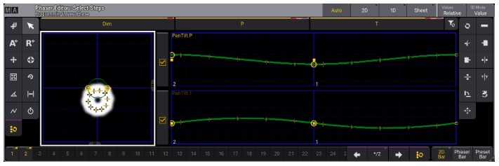
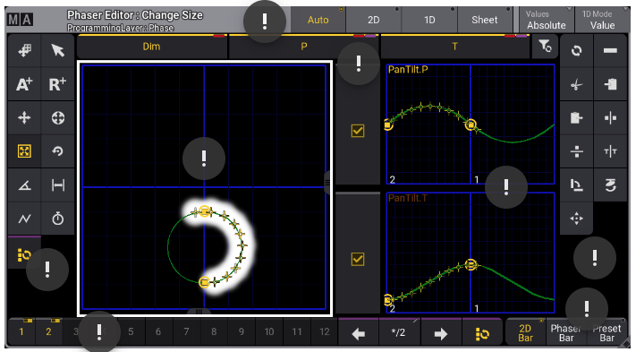
In the left toolbar you can find all tools which are important to create your phaser, e.g. add/delete steps, adjust the transition and phase or change the size.
The Step bar gives you the possibility to select and deselect Steps. It enables you to perform changes either to all Steps or only to a selection of Steps.
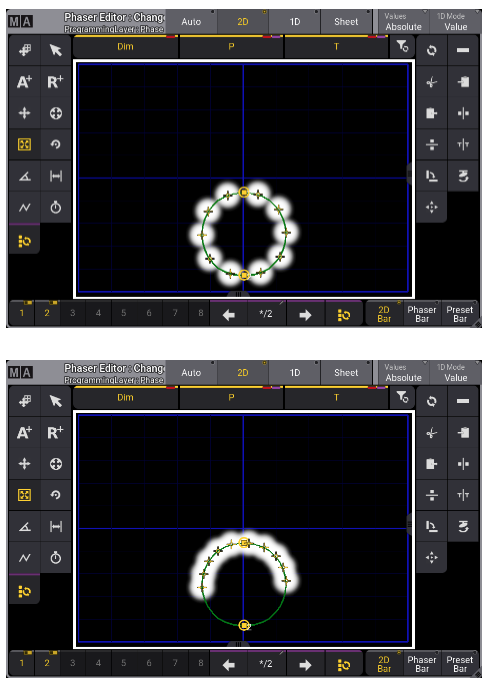
This is the 2D layout of the phaser editor. Here you can see a graphical representation of the position movements in your phaser. The horizontal axis shows the pan attribute, the vertical axis shows the tilt attribute.
Furthermore you can get information about the dimmer value and the color of your fixtures.
In the title bar you get some useful information - you can see which tool is currently selected and which layer you are working in. You can also switch between different layouts of the Phaser Editor or decide whether you want to work with Absolute or Relative values.
The layout shows Auto per default - here you will see the 2D and the 1D layout combined.
Using the Attribute Filters and tickboxes, you can filter attributes that you don't want to modify or store.
This is the 1D layout. Here you can see the Steps of all attributes in your Phaser in detail. The green curves are a graphical representation of settings like Transition, Acceleration and Deceleration for the Steps.
In the right toolbar you can find additional tools which can be used together with the tool selected in the left toolbar.
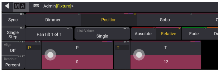
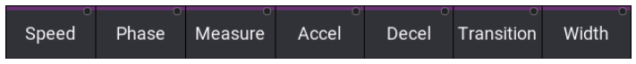
Here you can change the layout of the Encoder Bar when working with the Phaser Editor.
Position Phaser
We will go ahead with some Position Phasers, so our fixtures will start moving now. Let’s see how we can easily create a simple Tilt movement and a circle manually with the Phaser editor.
Absolute vs. Relative
So far most things we did were about Absolute values. We stored Position or Color Presets with Absolute values and we created our Phasers with Absolute values.
But we can also use Relative values. You can find them in our Encoder Bar, next to the Absolute value layer.
Relative values will be added to the Absolute values, together they will result in the actual output value. Relative values can be positive or negative, so you can increase or decrease the output by using Relative values. This is especially useful for positions. Think about a Relative circle which should move around a static Absolute center position or around the drummer position.

Use existing Presets as Steps
Let’s assume we have stored some nice static Color Presets and we would like to create a Phaser that uses the colors from these Presets. This is very easy to achieve:
- Select the Fixtures that you would like to work with (note that you need Color Presets that work for these Fixtures)
- Press the [Step] key (X5 in the Xkeys section)
- Call the Color Preset you would like to use in the first Step
- Repeat 2 and 3 to add more Steps with different colors
As a result, you will have a Phaser running across all the colors you selected. Store your programmer content as another Preset to recall it at any time.
Of course, this works for all other attributes
Phasers with MAtricks
You remember the MAtricks as a wizard for everything we do in the Programmer? Of course we can make use of this when we deal with Phasers as well.
In the video you can see some examples to adjust your Phasers live using the MAtricks!